What do you need?
- Nick’s VTS/V2 Hybrid Layshaft
- Team Associated V2 Slipper Pad
AS9611 or compatible
– or –
Revolution Design Ultra Vented Slipper Pads AE/YOK
RDRP0426 or compatible - Team Associated FT V2 Slipper Spring & Washer
AS7486 or compatible
– or –
Team Associated RC10B6.3 HD Slipper Spring and Adapters
AE91891 or compatible - RW Racing Associated B4 48dp Spur Gear (100T)
The ‘Lazer ZXR 100t Slipper Spur Gear with B4 pad’ might work as well, but needs at least a conversion bearing in the center as it has a larger hole. - Kyosho LA-11 (Drive Pulley Set)
– or –
Alcyon’s PP LA-11 F & R (3D printed through shapeways) - 2 pieces of 8x14x4 Bearings
standard Kyosho Lazer gearbox bearings
Option 1: Ruddog parts (metal)
It looks like these parts have been discontinued, although some stock remains.
- Revolution Design B5RM/MM VTS Slipper Option Kit
RDRP0254 or compatible - Revolution Design Ultra Vented Slipper Pads AE VCS
RDRP0427 or compatible
Option 2: Team Associated original parts (composite)
These parts aren’t as resistant to heat as the above metal parts. Some parts have been discontinued.
- Associated FT V2 Slipper Hub
AS7485 or compatible - Team Associated VTS Slipper Conversion
AS91199 or compatible
(Recommended) extra’s
- 1 x Kyosho LA-5 small guide plate
- 8mm inner diameter shims
0.1 to 0.3mm depending on your needs - 2 x M3 Nyloc nuts
Assembly Instructions for the layshaft and gearbox:
Explanation comes first, then you will find the accompanying picture
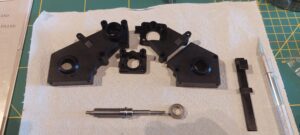
Below is the gearbox casing, layshaft and standard 8x14x4 bearing.
Notice the plastic part on the right is the belt guide that was featured on the Lazer ZX-Sport. This can help keep the belt in place when using low turn motors. It is also recommended to use a belt tensioner, this is outside the scope of this manual.
Put the bearing in the outside gearbox half (large part) as instructed in the Kyosho manual. Slide the layshaft through the bearing from the outside of the gearbox.
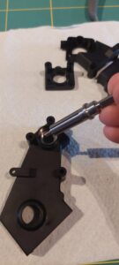
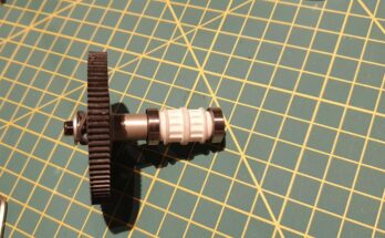
Slide the correct rear drive pulley onto the layshaft from the inside. Refer to the standard Kyosho manual.
Note: we are using white pulleys here as provided through shapeways (Alcyon’s pulleys mentioned in the list of parts).
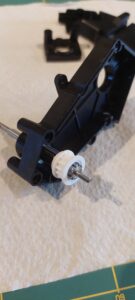
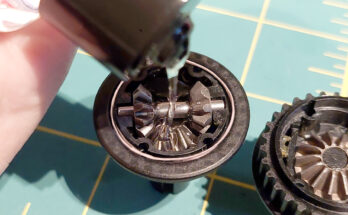
Follow the instructions in the manual to fit the short rear drive belt around the mounted pulley and fit the rear differential. Do not forget the LA-10 belt rollers or use alternative same-sized needle bearings.
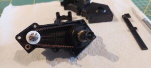
You can now mount the smaller gearbox half.
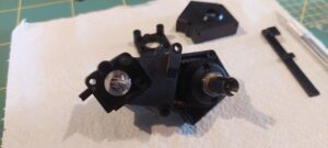
Mount the front drive pulley. Refer to the original Kyosho Lazer manual.
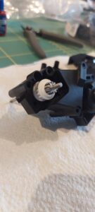
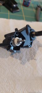
We mount a shim now, 8mm inside diameter, to locate the pulley against the bearing that we will add later. The pulley should be almost unable to move after assemble of the entire gearbox. You may want to disassemble later to choose a wider or narrower shim, or to add more shims. In this case, a 0.2mm shim was used, which is a good place to start on new parts.
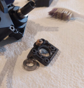
Prepare the plastic bearing carrier: insert the bearing into the recess and don’t forget the belt rollers. Follow the standard Kyosho Lazer manual.
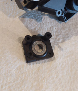
You can now mount the front drive belt.
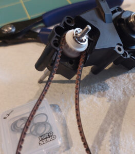
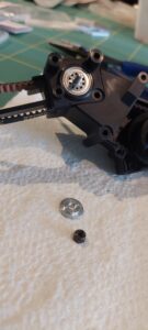
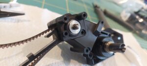
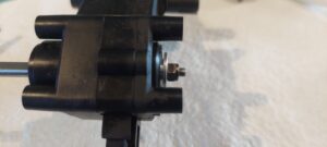
Mount the bearing carrier. You can fit a normal washer that fits around the layshaft thread while covering the bearing or you can opt to use the standard LA-5 small guide plate. You can install the LA-5 in either direction: small part outside to protect a bit more against dust entering, or small part inside (as pictured) as to not trap dust inside and ensure engagement to the inside ball race only. Use a Nyloc nut to tighten down until the layshaft is fixed into place. Be careful not to overtighten: avoid pressure on the assembly.
Option 1 assembly Instructions for the slipper setup
We will be using the Ruddog parts here. Detailed pictures for the original Team Associated parts can be found further in this document.
These are the parts you will be using for the slipper setup itself. They are layed out to demo the order and orientation of assembly from top left to right, then down and again from left to right.
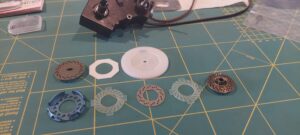
Once more the parts, in the order in which you will be assembling them.
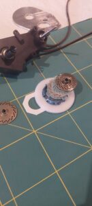
- Click the hexagonal slipper pad into the recess on the rear of the spur gear
here: pictured below and beside the spur to note the pad should be on the rear of the spur - Click the blue slipper cage onto the outside of the spur
- Position one of the round (with legs) slipper pads into the metal slipper part
- Position the middle disc onto the pad
- Position another round pad onto the middle disc
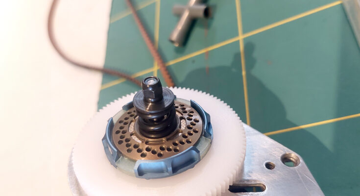
- Position the outer hub onto the pad, it should lock into the oval hole of the middle disc.
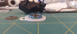
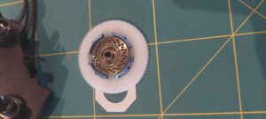
Mount the motor plate, follow the instructions in the standard Kyosho Lazer manual.
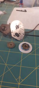
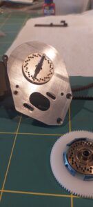
Slide the entire spur and slipper assembly onto the layshaft.
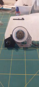
Next, position the spring, spring washer / guide and locknut.
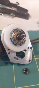
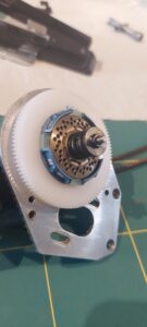
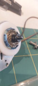
Option 2 assembly Instructions for the slipper setup
We will be using the Team Associated parts here. Pictures and instructions by Nick Mather.
Install the octagonal slipper pad and vts slipper cage on opposite sides of the spur gear. The slipper cage snaps into place with a little force.

All parts are layed out below.

Insert the slipper pad into the slipper cage

Insert the middle disc into the slipper cage.

Insert the second slipper pad into the slipper cage.

Install the outer slipper hub. Ensure the part locks into the oval shape of the middle disc.

Install the motor plate

Slide the inner slipper hub onto the layshaft. Note the orientation of the slot.

Locate the entire spur and slipper assembly onto the layshaft. Again line up the orientation of the slots.

Install spring, spring guide plate / washer and nyloc nut.

Adjusting the slipper
This is outside the scope of this manual. As a main guide, the slipper will protect your drivetrain from damage when suffering from high loads like when landing from jumps or when braking or applying throttle on uneven terrain. It can also help to keep grip when applying throttle using very powerful motors, although many ESC’s feature boost control for this.
As a general rule, when applying full throttle from a standstill you should hear your slipper slipping for up to a few metres. Too tight and you will lose the main slipper functionality (protect the drivetrain from external force on the wheels or from the motor), too loose and your slipper and / or spur will wear / overheat / melt. You will need to adjust according to your preference, depending on the surface and your driving style.
This manual
This document was created by Klaas De Waele, based on the original manual by Nick Mather and featuring his pictures for the ‘option 2’ original Team Associated VTS slipper parts. Other images (assembly of layshaft into the gearbox and Ruddog slipper assembly onto the layshaft) were taken by Klaas De Waele.
This version of the manual features the latest permanent 4×4 layshaft for the Lazer. See the images below.
Left
Original version of the layshaft, integrating the splined rear drive hub (originally LA-6) into the layshaft. Only the rear drive belt pulley will slide onto the layshaft. The rest of the setup features mostly parts of the ZX version of the Lazer (LA-9 thrust bearing and original LA-7 front drive hub with LA-5 small guide plate)
Right
Permanent 4×4 layshaft, integrating both splined rear and front drive hubs into the layshaft. Both pulleys slide onto the layshaft.

The layshafts were especially made to accept the VTS v2 slipper by Team Associated.
Other slippers may fit but haven’t been tested. If someone wants to look into this, I can only suggest (but not guarantee any compatibility) to look into these should you have them available to you. You may be able to see whether they slide onto the layshaft and if you can come up with an assembly of parts that works.
- Exotek MK3 Turbine Slipper
- Triad Evo Slipper
- Schumacher 3 plate slipper setup (U4670, U8502, U8399, U8423, U4674, U4673 and pads)
- Serpent SRX2 slipper clutch (50501)

