The basic idea
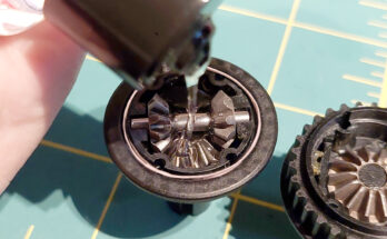
The main thing I was planning for this build was to use the fixed 4×4 layshaft Nick Mather produced in combination with the B4/5 VTS slipper produced by Revolution Design. Since this setup already sets a trend, I decided to include a lot of the racy parts that had come into my possession over so many years. And probably order some more…
Contrary to my Fibre Lyte Carpet Lazer I decided to go for a layout where a shorty battery would be located lengthwise along the chassis so I had more room for the ESC I was planning to use.
Build session 1
My base car would be the very charming Lazer ZX-Sport. It’s actually a derivative that Kyosho produced after the ZX-R. It’s the base model with a Kelron chassis and top deck, and uses the Triumph layshaft with a specific permanent 4×4 front-rear combined pulley and a plastic spur mount without slipper. The cars can be found at fairly low prices: about half the cost of a ZX-R.
Quite some of my ‘wants’ would be covered through the Exo Design Lazer ZX conversion kit. It features a carbon chassis and top deck, shock towers, different possibilities to fit the shorty Lipo (lengthwise or transverse), titanium turnbuckles, quite some screws and other stuff, and new belts.
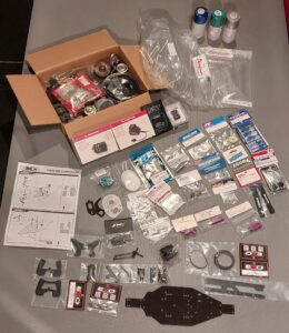
I went for the lengthwise installation of the shorty, which gave me a few small headaches.
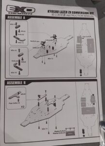
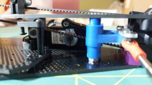
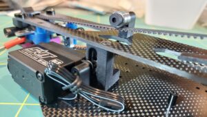
Exo Design was very responsive through messenger as I questioned them about how to connect the servo to the steering crank. You will see (top right) that you need to install a supplied extension post, which is a 5 x 8mm black metal tube which takes m3 screws both sides. The servo sits very close to the belt. Even when the SRT doesn’t have a massive top, I needed to find a very slim horn. I also needed to cut off the top of the horn to fit under the deck. This wasn’t made easier by the fact you absolutely need to use a metal horn, because the extra leverage created by the metal post that goes through the belt will most definitely bend any plastic that would be in the loop. I cut down the horn and drilled a hole where it was best.
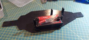
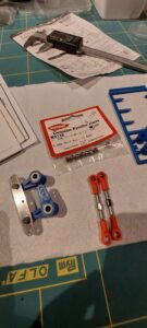
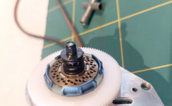
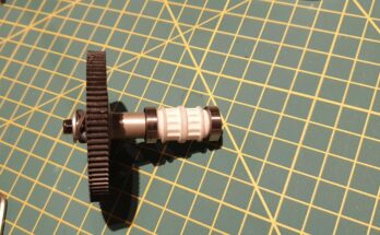
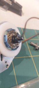
As mentioned, I used Nick Mather’s permanent 4×4 layshaft with a Revolution Design VTS v2 slipper. The spur is produced by RW Racing in the UK and features the B4 octagonal shaped slipper pad recesses. The slipper cage clicks into the recess of the spur. The white pulleys are the ones available through shapeways. If you order these, order the LA-11-F and LA-11-R parts. Do NOT used the LA-11-TW combined pulley as this will not slide over the layshaft due to having a ridge in the middle. Alcyon is planning on providing an alternative version for Nick’s layshaft.
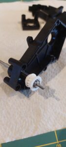
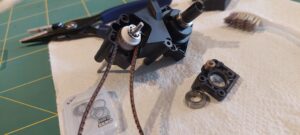
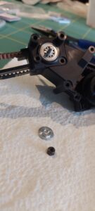
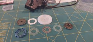
The centre deck post is also from shapeways. It comes with a belt tensioner feature. Due to the servo position and using the Lazer ZX-Sport belt guide in the rear gearbox I couldn’t really tension it fully, but I’ve added a second tensioner on the top deck using a slightly cut down servo post on the top deck. I had to cut the shapeways center post in half due to the battery being where it is, so just keeping the tensioner mount part.
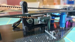
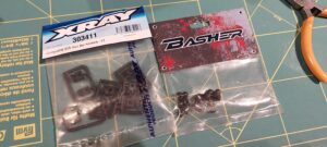
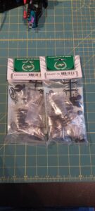
Another challenge were the purple pivot brackets. I had some of these for the rear as well but the rearmost can’t be mounted in any way, these didn’t seem to be made for the Lazer. Small mistake in the packaging probably. So I went with the Factory Works silver ones there. At the front, I had to shave 2mm off the suspension shafts using a file. And due to the Exo Design carbon parts being so thick I had to use 2mm longer screws all over the place.
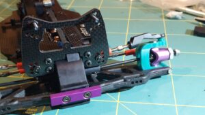
The Teamline hubs always need a bit of fiddling. I widened the holes slightly with a file and had to scrape some material off in several places to have no binding.
The purple knuckles weren’t that friendly either. One needed the bearing to be forced in a bit using (soft) pliers and needed no shimming. The other side needed a 0.3mm shim on the universal joint to have the OT-19 hex engage correctly without play.
I also found out the 2014 Scorpion 5.8mm ball studs are probably 5.85mm because they bind in the LA-43 ball ends. The W-0136 hard balls and original OT-31, OT-32, OT-36 and OT-101 are not a problem.
It feels a bit weird sometimes to open these packages that have been sitting around for ages. Selling them would probably have been the more sensible thing to do financially. But let’s just have some fun, okay?
I’ve also ordered some more hex hardware to swap over some of the screws, but self tappers with round head seem hard to come by in hex. The 2022 Optima Mid does feature some.
It’ll be a couple of days before I can get to the next step. I’m enjoying every single minute, going very slow and trying to not ruin some parts that need a modification while only having 1 chance to get it right.
Build session 2
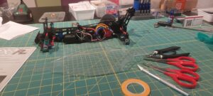
Moved on a bit in the build. Have fitted the rear arms, motor and all electronics, including setup with the transmitter.
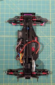
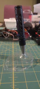
The rear dogbones were fitted using o-rings in the axle cups. I used a regular paper punch to make some sticky felt circles from furniture felt which fit perfectly in the OT-5 outdrives.
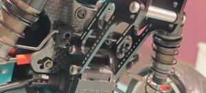
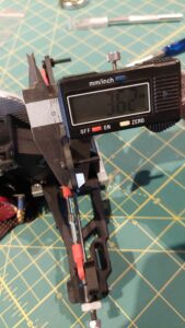
I’ve measured up the carbon so you can see the thickness of the EXO RC shock towers and decks.
The electronics are a 10BL120 Hobbywing esc with a matching 6.5t 5750kv sensored brushless motor. As I’m running just 2s, the motor shouldn’t run too hot so I went for a large 26t pinion.
I’ve used a 25t pinion on an 8.5t Hobbywing QuicRun 3650SD (4560kv) before which pulled wheelies on carpet. So just using that as a baseline.
The Futaba receiver is a telemetry version. I have to set up the ESC features still, initial throttle range is done already and the steering end points have been set. I have a program card to make the ESC setup a bit easier.
I’m not one to do too much cleaning up the receiver wiring etc. It’ll just stay like this. I’ve been using the Halko soldering jig 4 times now and while I like it more than the classic soldering hand, it’s already failed me: the plastic tensioning part lost its thread rather quickly. I’ve sent a message out to EuroRC and they’ve send me a second one. I have no high hopes for the durability of the part, and I’ve now also bent away the teeth of the jig clamps as they damage wiring because the springs on them are very strong.
I actually suspect I might switch to the regular metal OT-16 (or OT-211) knuckles as they have a cutout to go around the c-hubs – I don’t think the current steering angle is enough when the knuckles touch the Teamline c-hubs. I’ll figure it out once the wheels are fitted.
Up next will be the wing and shocks. And then I’ll investigate the pictures James Instone took to try and fit the Tomcat body as cleanly as possible.
Build session 3
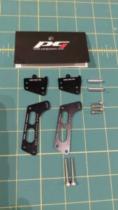
The Pargu wing stay was mounted, although I may replace the supplied screws with different (black) ones in the future.
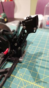
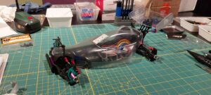
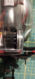
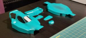
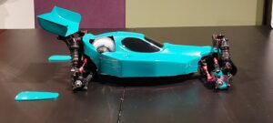
From Penguin Custom Bodyshells I bought the Tomcat body and the Procat and Bosscat wing. The body fits nicely as it’s made for the Kyosho Lazer and Tamiya Top Force, although I have to issue a warning: the lines for the spur cutout are off. The line that aligns to the inside of the motor plate, you should cut at least 5mm further to the outside of the car. (I ordered 2 new bodies from Penguin to correct this and I’ve recut a new one – picture illustrates the gap.) The other lines are quite okay but as I’ve fitted a different slipper I customised the cutout. And I’ve made modifications to the LA-35 spur cover.
I’ve also gone for a set of PR Racing shocks for their SB401 (78.5mm front / 93.5mm rear). They are a close match to the Kyosho Gold shocks for the ZX-R in terms of length, as those are medium fronts (75mm) and long rears (95mm). Short golds were 68mm. The PR shocks are big bores so they need some extra spacing between the shock stays and the pivot balls. The standard 5.8mm Kyosho balls go straight in which is a great plus to fit them in the arms. I’m quite happy!
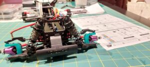
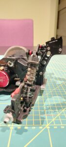
I used 400cts up front and 300cts at the rear but for broken terrain I could go softer for more absorption, probably 300 front and 250 rear or even 250 – 200. Also the springs while soft enough are also quite long so you can’t really get the car to sit really low, even with the spring stoppers fully screwed back. I’ve ordered the full spring set as well, but I’d prefer to cut them down or find shorter springs to have more ride height control.
Up next: it’s time for paint! And wheels.
Build session 4
The final chapter before running… Not being happy with my cutting of the body, 2 new ones were ordered from Penguin Custom Bodyshells.
As for the paint, I wanted to try out the Tamiya PS-54 Cobalt Green, maybe try make it a bit more blue (PS-39 translucent light blue) and add a bit of sparkle (PS-36 translucent silver). I did a few tests on a plastic bottle and settled on just a slight dusting of the silver and then the Cobalt Green. All was mounted using Kyosho magic tape (it’s velcro tape, wrongly advertised as being double sided tape) for sticking the undercowling to the bottom and Tamiya Egress velcro strips for the body.
The Penguin wing I used is for the Schumacher Procat, but I used different (Bosscat) end plates on it. I selected it from Penguin’s range and think it goes splendid with the body.
I honoured some of the brands I used with their stickers. I should add JC Racing Products as well who have supplied me with the tyres (and many wheels in the past).
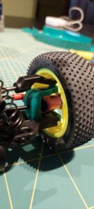
I followed James Instone and his recommendations of widening the front end using w-5063 UJ’s (NIB ones were found in my boxes, marked as spares for the Zaboon) and moving the Speedline hubs outwards. At the rear, for the tie rod he recommended the outer holes on the hub. I’ll try it like that, but might follow his suggestion to also move the ball joint to the inner hole on the tower, parallel to the dogbone, if I’d need a more docile grippy rear.
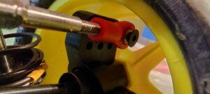
Another thing I’m mindful of is James’ rear belt tensioner. The way he built it, is to add strips of carbon both sides of the gearbox and cutting part of the gearbox. This allows an axle to be mounted through the strips and a bearing to be tensioned up against the top of the rear belt. I might try to replicate it… Or come up with something in the style of the rere Optima mid using a concentric setup.
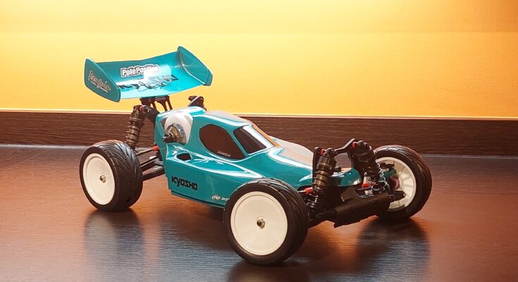
I’m really excited about how this came out. The body is such a gem. I followed James Instone’s racer as an example for this car – consider it a tribute to a great racer and one of the guys I idolised when I was a young kid. He’s a fantastic example for the community we find ourselves in. Thank you James! I hope we will once meet in person.
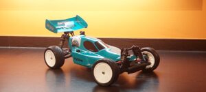
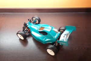
I can only say that for me the Lazer is an all time great. I have come addicted to it after I got my ZX-Sport when I was young, as a replacement for my crashed Grasshopper 2. I have the full range with the ZX, ZX-R, ZX-R mk2, ZX-RR and ZX-Sport as well as some modified examples and will definitely not pay the price for a ZX-S unless I win the lottery. Then I’ll buy 3.
Extra modifications
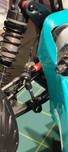
I’ve decided to add rear anti-roll bars.
